- Lasers
- Laser Parts
- Laser Machines
- Instrument & Measurement
- Optics & Crystals
- Fiber, Fiber Optics & Probes
- Acousto- & Electro-optic Devices
- Laser Accessories
LATEST NEWS
- Principles and Applications of Micro-Nano O
- Sintec Attended 2024 Asia Photonics Expo
- Sintec successfully participated in Laser W
- Sintec successfully participated in Laser K
- Sintec successfully participated at LWOP Sh
- Christmas and New Year Sales
 > Laser Parts
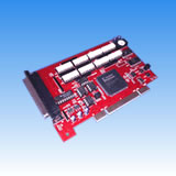


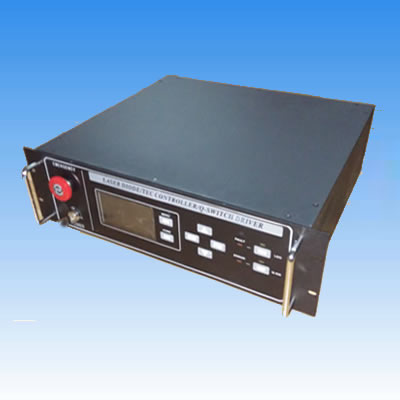
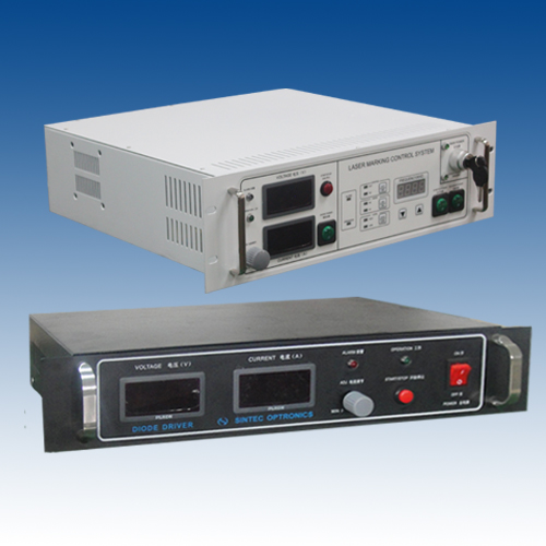
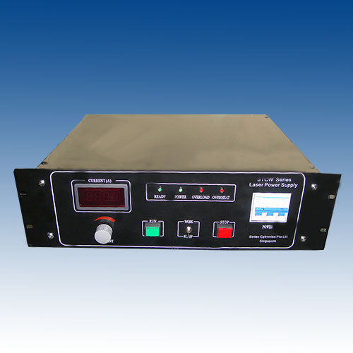
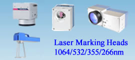
Laser Marking Control & Software
- Easily control all laser marking
- Suitable for YAG, CO2 & fiber laser marking
- The software can create various objects
- Easy operation
PRODUCT DESCRIPTION
Our marking software has been designed to meet the needs of all types of users of laser marking systems. The software was developed to be a retrofit package for existing systems, or as original software on new systems. The package provides significant advancements over previous laser marking control systems, while remaining extremely user-friendly. It's an object oriented, graphically interactive, PC control system providing a user the ability define and execute laser marking jobs. Multiple hardware interfaces are supported giving the software the ability to control most Nd:YAG and CO2 laser marking systems.
Unlike some marking software, the operator never has to remember what fonts and logo's need to be loaded for a particular job. The software automatically performs all required graphic loading. The software does not require users to learn any programming languages or special codes, and yet the software provides all of the flexible, graphic control users are accustomed to, including radial marking, aspect control, character spacing, angular rotations, and full justification. Text to be marked can be fixed or variable. Variable text can be retrieved at runtime from a variety of sources including, the keyboard, a bar code reader, and disk files. Automatic date coding and alphanumeric serialization are included as variable text types. Fonts include laser engraving fonts and Window’s True Type fonts. True Type fonts can be vector filled using user specified density, angle and kerf. Graphics (sometimes called "logo's" on other systems) can be imported from a large variety of common vector formats. All graphic features are either menu controlled or graphically controlled via the mouse and keyboard.
The software can create various objects such as barcode, DataMatrix, text, simple geometrical objects (such as line, rectangle, round-corner rectangle, polygon, circle, ellipse etc), complex graphic objects (such as PLT & BMP files), automatic date coding and alphanumeric serialization.
There are three types of marking cards (interface cards) and relevant software: LMX series, LMM series and LMC series. LMC can operate with Windows7 but others can not.
1. LMX Series Cards and Software
LMX Marking Control Card is especially developed for scan head and laser control in real time with a PCI bus interface. It is used with corresponding software to control laser marking.
● 2 analog output ports ( for scan head );
● 1 laser switch signal(TTL);
● 1 PWM signal(TTL);
● 9 digit input signals;
● 4 output signals(relay output);
● 2 differential mode axes control for step/servo motor;
● 1 single ended mode axe control for stop/servo motor;
2. LMM Series Cards and Software
LMM Marking Control Card is especially developed for scan head and fiber laser control in real time with a PCI bus interface. It is used with corresponding software to control laser marking. The suitable fiber lasers are IPG, Manlight and SPI lasers via 8-bit laser power adjustment.
● 2 analog output ports ( for scan head );
● 11 digital output signals, TTL/CMOS compatible;
● 7 digital input signals TTL/CMOS compatible;
● 1 PWM signal output (TTL).
There are following main functions of LMM marking software:
Operation under WINXP/2000
Acceptable for PLT and BMP
Support drawing such as circle, rectangle, line etc.
Support the edit of SHX and TTF fonts
Barcode, 2D DataMatrix, series numbers, date, time
Support the layers up to 8
Save of all system parameters
Support copy, delete, replace, move etc
Support mirror, hatch, group
Set pulse repetition rate, pulse duty factor
Control ON/OFF, laser power of CO2 lasers from Synrad, Coherent, Universal Lasers, Manlight and IPG etc.
3. ETH6608 Series Cards and Software
The ETH6608 card, which is designed to provide a standalone platform with Ethernet communication to PC, allows the capability of more devices configuration, and is more compatible solution in laser marking or engraving applications. Marking data can be downloaded by using a RJ45 interface with default IP address 192.168.1.55, and the PC to be set under 192.168.1.X.
Due to the configuration flexibility, there are four models available to different requirements: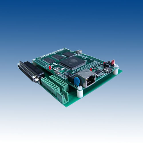
ETH6608A1_5/10, to control 1 analog scanner via ±5/10VDC
ETH6608A2_5/10, to control 2 analog scanners via ±5/10VDC
ETH6608A1D1_5/10, to control 1 analog scanner via ±5/10VDC, and 1 digital scanner
ETH6608A2D1_5/10, to control 2 analog scanners via ±5/10VDC, and 1 digital scanner
In its standard configuration, the ETH6608 consists of a base board with the following features:
• 100MBits Ethernet connection
• Compatible with digital scanner head
• Four 16-bit DAC output, selectable voltage output to control analog scanner
• 16 channels TTL compatible digital input
• 21 channels TTL compatible digital output
• 6 channels hardware limit inputs, to control motion
• Special instruction for pulse number
• 1 differential PWM output, minimum 10ns pulse width
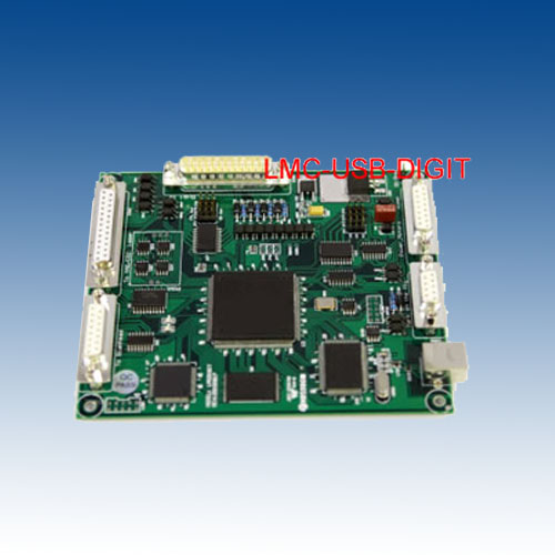
4. LMC Series Cards and Software
Our marking software has been designed to meet the needs of all types of users of laser marking systems. The software was developed to be a retrofit package for existing systems, or as original software on new systems. The package provides significant advancements over previous laser marking control systems, while remaining extremely user-friendly. It's an object oriented, graphically interactive, PC control system providing a user the ability define and execute laser marking jobs. Multiple hardware interfaces are supported giving the software the ability to control most Nd:YAG, CO2 and fiber laser marking systems such as adjusting currents, frequency, duty ratio . and red light indication.
Unlike some marking software, the operator never has to remember what fonts and logo's need to be loaded for a particular job. The software automatically performs all required graphic loading. The software does not require users to learn any programming languages or special codes, and yet the software provides all of the flexible, graphic control users are accustomed to, including radial marking, aspect control, character spacing, angular rotations, and full justification. Text to be marked can be fixed or variable. Variable text can be retrieved at runtime from a variety of sources including, the keyboard, a bar code reader, and disk files. Automatic date coding and alphanumeric serialization are included as variable text types. Fonts include laser engraving fonts and Window’s True Type fonts. True Type fonts can be vector filled using user specified density, angle and kerf. Graphics (sometimes called "logo's" on other systems) can be imported from a large variety of common vector formats. All graphic features are either menu controlled or graphically controlled via the mouse and keyboard.
The software can create various objects such as barcode, DataMatrix, text, simple geometrical objects (such as line, rectangle, round-corner rectangle, polygon, circle, ellipse etc), complex graphic objects (such as PLT & BMP files), automatic date coding and alphanumeric serialization.
Digital card (control CO2 laser, YAG laser)
Data transfer:usb2.0 interface
Digital output used for scan head
Support FPK with three ways [optional]
Support high-speed fly marking with rotary encoder
Eight digital input and seven digital output used for other controlled equipment
25 routes general digital signals(TTL compatible), 4 of the IO ports can be OC IO, can connect with relay.
LASER Signal: TTL, used for laser On/Laser Off .
PWM Signal: TTL, used to adjust the frequency and duty ratio.
Tow Direction/Pulse signals, used to control stepping motor.
START Signal: used to connect foot switch
SPI G3.0 card (control SPI laser)
Use 68-pins SCSI 3 socket, connect SPI G3 laser module via 68-pin cable directly
Adjustable digital/analog output used for scan head
Mark-on-fly function with an encoder connected
Extend axes output: Two Direction/pulse signals, used to control stepping motor or servomotor
25 routes general digital signals(TTL compatible), 4 of the IO ports can be OC IO, can connect with relay
Original start signal: Used when marking contents are the same and high speed is required
Compatible with USB2.0
IPG CARD (control IPG-YLP laser and IPG-YLPM laser)
Use 25-pins DB25 socket, connect IPG YLP and YLPM laser module via 25-pin cable directly
Adjustable digital/analog output used for scan head
Mark-on-fly function with an encoder connected
Extend axes output: Direction/pulse signals, used to control stepping motor or servomotor
25 routes general digital signals(TTL compatible), 4 of the IO ports can be OC IO, can connect with relay
Original start signal: used when marking contents are the same and high speed is required.
Compatible with USB2.0
Dynamic focus board
Dynamic focus .three digital output for scan head
Support FPK with two ways (optional)
6 routes digital input and 6 routes digital output
LASER signal : TTL, used for laser on/laser off
PWM signal: TTL ,used to adjust the frequency and duty ratio
Direction/pulse signals ,used to control stepping motor or servomotor
DB25 connector used for IPG YLP laser directly (optional)
Compatible with USB2.0
5. DIGI-STRUCT Laser Markng Controller
l Increasesproductivity & flexibility
l Saves time& material
l Easier tocustomise
l Minimisesdowntime
l Eliminatesprogramming error and interference with laser marking
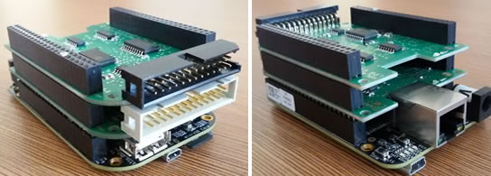
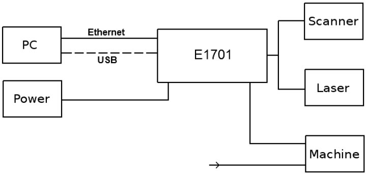
The laser marking controller consists of E1701D scanner controllerbaseboard plus optional extension boards. The E1701 scanner controller boardsare designed for controlling galvanometric scanner systems with two or threeaxes. Depending on the used extension boards (which are optional) they alsosupply extensive signals for laser and external control. The communicationbetween the host system and the controller boards is done via Ethernet or USB.
When using E1701 scanner controller boards, there is always onebaseboard required for proper operation.
This baseboard can be used together with different extension boards thatprovide additional signals for
controlling the laser marking process. These extension boards areoptional and have to be used only in
environments where the additional signals processed by these boards arerequired. So depending on used type of laser and requirements, the minimalsolution to control a laser marking system may consist of the baseboard only.
Normally extension boards can be combined with any baseboard and allother extension boards freely, there
are no restrictions for usage. In case some specific extension boardtypes can’t be operated with other boards, Normally an E1701 baseboard can becombined with several extension boards of different types but not with morethan one board of same type. In case of special extension boards where morethan one board of the same type can be used, this is stated in description ofthe related boards below.
E1701D XY2/100 Digital Laser Scanner Controller Baseboard
This baseboard can be used to control 2D or 3D scanheads that come witha XY2/100 interface. It can be
combined with extension boards without any restrictions. E1701D offersfollowing features:
l XY2/100 interface to scanhead with X, Y and Z channel
l 100 Mbit Ethernet connection
l USB 2.0 connection
l online XYZ grid correction with support for several correction tablefile formats (like SCAPS(tm) .ucf,
l Scanlab(tm) .ctb and .ct5, Raylase(tm) .gcd)
l switching between up to 16 grid correction tables during marking process
l high-definition online XYZ grid correction with BeamConstruct HDcorrection files (.bco)
l 10 microseconds vector cycle time and resolution (microstep period)
l command execution time down to 0,5 microseconds
l realtime processing of laser and scanner signals
l 26 bit internal resolution (for better quality also with 16 bit hardwareoutput)
l can control nearly every laser type (this may require extension boardsas described below)
l two laser CMOS digital outputs for usage with YAG, CO2, IPG(tm), SPI(tm)and compatible laser types
l (outputs can provide PWM frequency, Q-Switch, FPK-pulse, CW/continuouslyrunning frequency,
l stand-by frequency) running with frequencies of up to 20 MHz
l 512 MByte DDR3 RAM
l 1 GHz CPU clock
l support for Micro-SD and Micro-SDHC cards
l internal command and vector data list with more than 20 million entries
l continuous list concept, no need to swap between lists
l BeamConstruct PRO license included
l open source compatibility library that emulates existing programminginterface for fast and easy usage
l with existing software (contains e.g. Scanlab, RTC4), SCAPS, USC/SCI andother compatible interfaces)
E1701 LP8 Extension Board
This board can be used to provide signals for controlling a wide rangeof laser types. It offers following features:
l LP8 8 bit CMOS level parallel digital output e.g. for controlling laserpower
l LP8 latch CMOS level digital output for usage with IPG(tm) andcompatible laser types
l Master Oscillator CMOS level digital output for usage with IPG(tm) andcompatible laser types
l 8 bit 0..5V analogue output e.g. for controlling laser power (thisoutput is a slave of LP8 outputs)
l two laser CMOS level digital outputs for usage with YAG, CO2, IPG(tm),SPI(tm) and compatible laser
l types (outputs can provide PWM frequency, Q-Switch, FPK-pulse,CW/continuously running
l frequency, stand-by frequency) running with frequencies of up to 20 MHz
E1701 Digi I/O Extension Board
This board provides additional digital in- and outputs forsynchronisation and communication with external
equipment. It offers following features:
l 8 freely usable digital outputs providing either CMOS level orelectrically insulated outputs via
l external power supply
l 8 freely usable digital inputs expecting either CMOS level orelectrically insulated inputs via external
l power supply
l 2 digital inputs usable for quadrature encoder signals for markingon-the-fly applications
E1701 Secondary Head Extension Board
Using boards of this type additional heads can be connected which thenwork in parallel to the first scanhead of E1701D baseboard. So as only outputit provides an additional XY2/100 connection.
Software Features
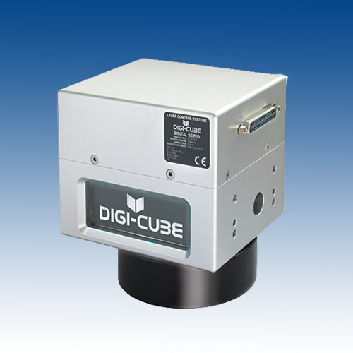
The Digi-Struct is featurerich software platform that provides a user-friendly layout with an easy-to-useand powerful toolset for the creation of laser marking programmes and controlof Digi-Cube laser scan heads to further maximise productivity and reduceproduction costs
A vast array ofdifferent one dimensional and two dimensional codes are available frominstallation including QR codes, Datamatrix UPC and EAN.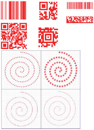
SupportsTrueType fonts, including Unicode, and a variety of different script styles.
Fulfils thedemands of an ever more globalised identification and labelling market.Digi-Struct also comes with 11 different laser vector fonts providing legiblecharacters in the fastest possible timeframe.
A large number of different date and time optionsare available.
Provides theultimate flexibility of date and time coding while remaining simple to usethrough a date/time wizard. Customisable date/time strings can also be madeusing a list of easily entered commands with minimal syntax.
Provides avariety of line styles, giving you full control of the laser marking process.
Perforation ofpieces can be achieved by a few clicks of a mouse and custom line styles areavailable to perform specific tasks.
Supports imagesand artwork in a variety of standard formats including .dxf and .svg.
Makes addinglogos and images to products quick and easy. With no tooling to consider,brands and logos can be changed,
Theautomated test matrix makes the fine tuning of your marks faster and easier.
This gives you the best possiblecontrast using the shortest amount of time and using as little material aspossible.
By utilising the automated testmatrix tool, a number of different effects created by the laser source can bemarked on to a single swatch of sample material and can easily be identifiedand refined using the grid within the automated test matrix.
3D capabilities allows for subtractive3D printing( removing material instead of adding ).
Utilises a versatile ‘Slicing’system, breaking down a complex 3D project into easy-to-handle 2 dimensionallayers.
Scan Head Controller –Software Board & Extension Boards
Combines a powerful 1GHzprocessor on a compact platform with a scalable architecture and low thermaloutput. This allows laser OEM’s to integrate the software into their currentdesign pipeline easily and efficiently.
YAG and CO2 lasers are supportedout of the box, whilst the easy-to-connect extension boards can be added tointerface with fibre laser sources such as IPG®, SPI®, iLuma®, Raycus and allother commercially available laser sources.
The Digi-Card sports a 100MbEthernet connection allowing for the rapid transfer of data between a PC andthe laser control software which is stored on the 4GB micro SD card containingall the laser marking programmes. The programmes can then be selected bysoftware commands or by utilising the I/O expansion board.
Control Box
An easy-to-use feature of theDigi-Struct Software allows up to 254 different laser marking programmes to becreated on a Laptop or Desktop computer.
These programmes can then bedownloaded on to a micro SD card and inserted into the Digi-Link Control Box.
When the Digi-Card Scan HeadController Board is connected to the Digi-Link it allows the user to select theappropriate programme and externally control laser stop/start functions,removing the need for a Laptop/Desktop on the shop floor -saving time,eliminating programming error and preventing any unauthorised access orinterference with the laser marking.
The Digi-Link control box can also receiveinstructions via an Ethernet connection allowing full factory integration.