- Lasers
- Laser Parts
- Laser Machines
- Instrument & Measurement
- Optics & Crystals
- Fiber, Fiber Optics & Probes
- Acousto- & Electro-optic Devices
- Laser Accessories
LATEST NEWS
- Principles and Applications of Micro-Nano O
- Sintec Attended 2024 Asia Photonics Expo
- Sintec successfully participated in Laser W
- Sintec successfully participated in Laser K
- Sintec successfully participated at LWOP Sh
- Christmas and New Year Sales

 > Fiber, Fiber Optics & Probes
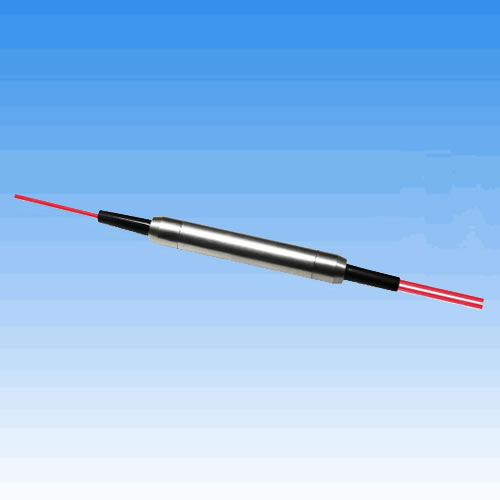


PM, Tap & Near Infrared Optical Coupler
- Low light loss
- High power handling
- No unwanted reflections
- 700 to 1150nm operation
PRODUCT DESCRIPTION
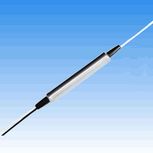
Near Infrared Coupler
The Near Infrared Coupler splits light at any selected wavelength from 700nm to 1150nm. Designed for applications in fibre laser, sensor and avionics applications, the coupler utilizes G&H’s low loss fused fibre technology. No light leaves the fibre and therefore no alignment is required; and there are no unwanted reflections. Furthermore the output fibre pigtails may be directly integrated into beam delivery systems. For components and modules which combine different wavelengths within the near infrared region please refer to the datasheet ‘Near Infrared WDM’.
Key Features:
700 to 1150nm operation
Any coupling ratio available
All fibre – no alignment required
No unwanted reflections
Low light loss
High power handling
Applications:
Fibre lasers
Sensors
Avionics
Biomedical equipment
Research
Optical Specifications
|
Coupling Ratio (%)3 |
Grade |
Available Wavelength(s) |
Available Housing Option |
Signal Path Insertion Loss (dB)1,2 |
Tap Path Insertion Loss (dB)1,2 |
|
1 |
A |
700 to 1150nm |
3,4,5,6 |
0.15 |
24.9 |
|
1 |
B |
700 to 1150nm |
3,4,5,6 |
0.20 |
25.3 |
|
5 |
A |
700 to 1150nm |
3,4,5,6 |
0.40 |
15.9 |
|
5 |
B |
700 to 1150nm |
3,4,5,6 |
0.50 |
16.2 |
|
10 |
A |
700 to 1150nm |
3,4,5,6 |
0.9 |
12.2 |
|
10 |
B |
700 to 1150nm |
3,4,5,6 |
1.1 |
12.4 |
|
20 |
A |
700 to 1150nm |
3,4,5,6 |
1.5 |
8.4 |
|
20 |
B |
700 to 1150nm |
3,4,5,6 |
1.7 |
8.6 |
|
30 |
A |
700 to 1150nm |
3,4,5,6 |
2.2 |
6.4 |
|
30 |
B |
700 to 1150nm |
3,4,5,6 |
2.4 |
6.4 |
|
40 |
A |
700 to 1150nm |
3,4,5,6 |
3.0 |
4.9 |
|
40 |
B |
700 to 1150nm |
3,4,5,6 |
3.2 |
5.1 |
|
50 |
A |
700 to 1150nm |
3,4,5,6 |
3.8 |
3.8 |
|
50 |
B |
700 to 1150nm |
3,4,5,6 |
4.0 |
4.0 |
1. In 2x2 couplers insertion loss is not specified for launch through second input port P4 (coloured blue)
2. Maximum insertion loss at operating wavelength. Not including TDL, PDL or connector losses.
3. Any coupling ratio available. Please contact us for specifications of coupling ratios not listed.
|
Parameter |
Specification |
Unit |
|
Operating Wavelength |
Specified wavelength within the range 700-1150nm |
nm |
|
Operating / Storage Temperature Range |
-40 to +75 / -40 to + 85 |
oC |
|
Pigtail Tensile Load |
5 |
N |
|
Fibre Type |
Speciality singlemode fibre |
|
1. For connectorised component, operating temperature range is –5 to +75oC.
Housing Option
|
Housing Code |
Description |
1x2, 2x2 Dimension(mm) |
Pigtail |
|
3 |
Regula |
3.0 (f) x 50 (L) |
Primary-coated fibre |
|
4 |
f0.9 mm slim |
3.0 (f) x 60 (L) |
f0.9mm loose-tube |
|
5 |
f0.9 mm semi-ruggedised |
5.0 (f) x 75 (L) |
f0.9 mm loose-tube |
|
6 |
f3.0 mm fully-ruggedised |
80(L)x10(W)x8(H) |
f3.0 mm fan-out sleeving |
Configuration
Ordering Code Information
1. FFS-780K31A10 (Fused Fibre Speciality Coupler, 780nm, 50/50 coupling ratio, regular housing, 1x2, A grade, 1m pigtails, no connectors)
2. FFS-060K31A10 (Fused Fibre Speciality Coupler, 1060nm, 50/50 coupling ratio, regular housing, 1x2, A grade, 1m pigtails, no connectors)
1. Minimum pigtail length. Further pigtail lengths available on request. Where connectorised, pigtail length is to connector end face.
2. Insertion Loss in specification table does not include connector losses.
3. Any coupling ratio available. Please contact G&H for ordering codes of coupling ratios not listed.
4. LC connector not available for housing code 6, fully ruggedised housing.
5. Connectors may be fitted to housing types 4, 5 and 6. For connectorisation of housing type 3 please contact the sales office.
PM Coupler
The G&H PM Coupler enables the accurate monitoring and splitting of optical signals in polarisation maintaining fibre. Manufactured using industry-standard PM fibre, the PM Coupler is available in any coupling ratio from 1% to 50%. Based on G&H’s fused fibre technology, the PM Coupler demonstrates very low loss, high power handling and there is no price penalty for adding a second input port. The centre operating wavelength may be chosen from within a wide variety of operating passbands, including 980, 1064, 1310, 14xx, 15xx and 16xx.
In common with all PM components, it is necessary to launch into either the slow or the fast axis to maintain polarisation. For the G&H PM Coupler, specifications are based on slow axis launch, although fast axis versions are also available if requested.
Key Features:
All PM fibre construction
Low excess loss
High power handling
980, 1064, C, L and S bands available
Slow axis operation as standard
Fast axis operation also available
Applications:
Power monitoring of PM sources
Coherent communications
Fibre gyroscopes
High power fibre lasers
Fibre amplifiers
Optical Specifications1
|
Parameter |
Specification |
Unit |
|||||
|
Centre Wavelength Range |
9xx |
10xx |
1310 |
14xx |
15xx |
16xx |
nm |
|
Available Wavelengths2 |
915-999 |
1000-1099 |
1310 |
1425-1499 |
1500-1599 |
1600-1650 |
nm |
|
Coupling Ratio |
1/99 |
% |
|||||
|
Coupling Ratio Tolerance |
+/- 0.5 |
% |
|||||
|
Extinction Ratio3, Grade A |
20 |
20 |
20 |
20 |
20 |
20 |
dB |
|
Extinction Ratio3, Grade B |
17 |
17 |
17 |
17 |
17 |
17 |
dB |
|
Coupling Ratio |
5/95 |
% |
|||||
|
Coupling Ratio Tolerance |
+/- 1.5 |
% |
|||||
|
Extinction Ratio3, Grade A |
20 |
20 |
20 |
20 |
20 |
20 |
dB |
|
Extinction Ratio3, Grade B |
17 |
17 |
17 |
17 |
17 |
17 |
dB |
|
Coupling Ratio |
10/90 |
% |
|||||
|
Coupling Ratio Tolerance |
+/- 3.0 |
% |
|||||
|
Extinction Ratio3, Grade A |
20 |
20 |
20 |
20 |
20 |
20 |
dB |
|
Extinction Ratio3, Grade B |
17 |
17 |
17 |
17 |
17 |
17 |
dB |
|
Coupling Ratio |
33/67 |
% |
|||||
|
Coupling Ratio Tolerance |
+/- 4.0 |
% |
|||||
|
Extinction Ratio3, Grade A |
20 |
20 |
20 |
20 |
20 |
20 |
dB |
|
Extinction Ratio3, Grade B |
17 |
17 |
17 |
17 |
17 |
17 |
dB |
|
Coupling Ratio |
50/505 |
% |
|||||
|
Coupling Ratio Tolerance |
+/- 5.0 |
% |
|||||
|
Extinction Ratio3, Grade A |
20 |
20 |
20 |
20 |
20 |
20 |
dB |
|
Extinction Ratio3, Grade B |
17 |
17 |
17 |
17 |
17 |
17 |
dB |
|
Excess Loss Grade A |
0.3 |
0.3 |
0.3 |
0.3 |
0.3 |
0.3 |
dB |
|
Excess Loss Grade B |
0.5 |
0.5 |
0.5 |
0.5 |
0.5 |
0.5 |
dB |
|
Return Loss/Directivity |
50 |
dB |
|||||
|
Pigtail Tensile Load |
5 |
N |
|||||
|
Operating Temperature |
-5 to +751 |
oC |
|||||
|
Storage Temperature |
-40 to +85 |
oC |
|||||
|
Fibre Type |
Polarisation maintaining fibre (industry-standard profile) |
|
|||||
1. All specifications are for operation at room temperature.
2. The centre wavelength may be selected from within the available wavelength ranges supplied.
3. Defined for signal path P1-P2.
4. Defined for both signal path P1-P2 and tap path P1-P3.
5. Preliminary specifications.
Configuration
Ordering Code Information
Example: FFP-CK3250A10 (C band, PM Coupler, 50/50 coupling ratio, regular housing, 2x2, channel centre =1550nm, grade A, 1m pigtail, no connector)
1. Channel centre must be within the wavelength ranges shown in the Optical Specifications table.
2. Minimum pigtail length. Other pigtail lengths are available on request.
3. Optical specifications in specification table do not include connector loss. Other connectors available on request.
4. Other coupling ratios available on request.
5. PM Products are manufactured using 250μm PANDA PM fibre, 400μm PANDA PM fibre available at wavelengths higher than 1400nm.
PM Low Ratio Tap Coupler
The G&H Fused PM LRT, taps off low power from a signal path whilst maintaining polarisation through the component. G&H proprietary PM manufacturing technology provides tap ratios as low as 0.01% with ultra low loss and high polarisation extinction ratio. The all fibre construction and excellent loss characteristics provide exceptional reliability at high powers. PM LRT’s also exhibit improved tap ratio stability when input polarisation extinction ratio levels are low or fluctuating.
These high performance parts are available at a range of wavelengths with different fibre options. PM LRTs can therefore be readily specified in a wide variety of applications, enabling rapid design cycles and new project builds.
Standard parts are available at wavelengths from 900 – 1600nm. For other wavelengths or coupling ratios please contact the sales office.
Key Features:
Low Loss
High PER
High power handling
PM PANDA Fibre on all ports
Applications:
Fibre lasers
Instrumentation
Optical Specifications
|
Parameter |
Specification3 |
Unit |
||||
|
Coupling Ratio |
0.01 |
0.1 |
1 |
5 |
10 |
% |
|
Tap Insertion Loss1 |
36 -44 |
27-33 |
18.2-23 |
11.9-14.9 |
8.86-1.85 |
dB |
|
Signal Insertion Loss1 |
0.3(Typ<0.1) |
0.3 (Typ<0.1) |
0.37 |
0.6 |
0.9 |
dB |
|
1300 – 1600 Signal PER2 |
>20 |
dB |
||||
|
900 – 1100 Signal PER2 |
>20 |
dB |
||||
|
Return Loss |
>55 |
NA |
||||
|
Operating Wavelength4 |
Any Wavelength from 900-1100nm and 1300-1600nm |
NA |
||||
|
Housing |
Regular Ø3.0 x 60 (max) |
|
||||
|
Fibre Type |
PM PANDA Fibre |
|
||||
1. Insertion Loss at operating wavelength. Not including TDL.
2. Devices manufactured to operate in fast axis as standard. For use in a slow-axis system a 90° PM splice is required.
3. Specifications shown are for operation at room temperature.
4. The centre wavelength may be selected from within the available wavelength range supplied.
Configuration