- Lasers
- Laser Parts
- Laser Machines
- Instrument & Measurement
- Optics & Crystals
- Fiber, Fiber Optics & Probes
- Acousto- & Electro-optic Devices
- Laser Accessories
LATEST NEWS
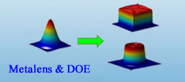
- Principles and Applications of Micro-Nano O
- Sintec Attended 2024 Asia Photonics Expo
- Sintec successfully participated in Laser W
- Sintec successfully participated in Laser K
- Sintec successfully participated at LWOP Sh
- Christmas and New Year Sales


 > Laser Parts
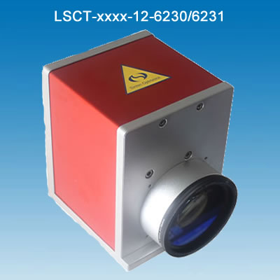


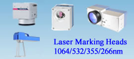
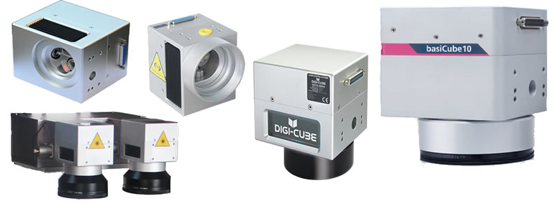
Scan Heads (Marking Heads)
- Full range of scan heads
- Reliable & easy operation
- Marking software matachable
- Cheap but high quality
PRODUCT DESCRIPTION
A wholelaser marking head (or called laser scanner) consists of two scan mirrors, twogalvanometers (or calledgalvo-scanner motor)& drive cards (or called driver), a XYmount, a scanning lens (f-theta lens), an interface card (or called D/A card), aset of marking software and a DC power supply.
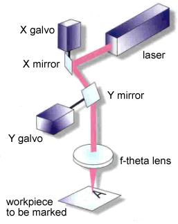
Basicsof 2-axis laser scanners
A laserbeam is reflected from two scan mirrors in turn, and directed through afocusing lens. The mirrors are capable of high speed deflection about arotation axis, being driven by a galvo-scanner motor. In most cases the maximumdeflection angle of the mirror is ±12.5° (often ±10° is a safer limit) eitherside of the non-deflected incidence angle of 45°.
Note that, for best performance, the lens willappear to be ‘the wrong way round’ when compared with a standard meniscus lensused in conventional focusing of a laser beam.
Someof the design objectives in specification of 2-axis laser scanners are:
* Achievementof desired scanned field size
* Maximizationof scan speeds
* Minimizingfocused spot sizes
* Lowestcost solutions
Someof the limitations to be considered are:
* QualityfactorQ(Q =M2) of the laser beam
* Scanangle limitations
* Lossof power due to beam-clipping
* Physicalaperture of the scanner head
Fieldof scan
The laserbeam will be scanned over an angleq,equal to twice the mirror deflection angle. So, the typical scanned field mightbeq=±20°in both X and Y directions. (q=±25°would be the usual maximum scanned field). The field size is then approximately2Ftanqin both X and Y.
Theapproximation arises because:
1) it is usually desirable to have adeliberate distortion characteristic inthe scanner lens design so that the field position is proportional toq, not tanq.
2)scanning in two axes produces a geometrical distortion which is unrelated tothe lens properties.
Focusedspot size
The lowerlimit on spot size ‘d’ (1/e2intensity diameter) for a laser beam ofdiameter ‘D’ (1/e2) is:
d= 13.5QF/Dmm
Example:A TEM00beam (Q=1) of13.5mm(1/e2) diameter, focused by a perfect lens of100mmfocal length, will form a focused spotof100mm diameter.(Taking a more realistic value of Q=1.5, the spot size would be150mm).
Beamclipping and optical aberrations can lead to focused spot sizes which arelarger than the minimum diffractionlimited value found from the equation above.
Largefield sizes demand the use of lenses of long focal length. In turn, this leadsto increased focused spot size unless the beam diameter, mirror sizes, and lensdiameter are all increased.
Spotsizes are given in the form of an average spot size over the whole, maximum,field-of-scan. A second figure, the standard deviation from average spot size,gives a measure of variation of the spot size to be expected over the field.
Part NumberDescription of Marking Head
Description of Part Number: LSxx-xxxx-yy-AAAA
LSxx: laser scanner. xxmeans series marking heads such as CT, SL, LC, JC.
xxxx: laser wavelength.
yy: maximum input laser beam diameter.
AAAA: notes or remarks
|
Max entrance dia. mm |
Model of galvo |
Dimension LxWxH,mm |
Control |
|
|
LSCT-xxxx-12-6230 |
12 |
CTI-6230 |
165x125x125 |
Analog input |
|
LSCT-xxxx-12-6231 |
12 |
CTI-6231 |
165x125x125 |
Analog input |
|
LSSL-xxxx-7-XS |
7 |
OSSL-XS |
79x69x78 |
XY2-100 |
|
LSSL-xxxx-10-S |
10 |
OSSL-S |
115x97x94 |
XY2-100 |
|
LSSL-xxxx-10-BC10 |
10 |
OSSL-S |
106x91x91 |
XY2-100 |
|
LSSL-xxxx-14-M |
14 |
OSSL-M |
134x100x106 |
XY2-100 |
|
LSLC-xxxx-10-DIGI |
10 |
|
115x97x97 |
XY2-100 |
|
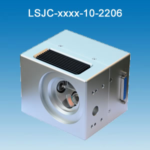
LSJC-xxxx-10-2206 |
10 |
|
119x97x94 |
XY2-100 |
|
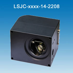
LSJC-xxxx-14-2208 |
14 |
|
126x98x105 |
XY2-100 |
Allabove marking heads can operate at 1064nm, 532nm, 355nm or 10.6um wavelength. Otherentrance diameters available upon request. Please contact us for moreinformation.
Remark:
* The marking fieldof markingheaddepends on the f-theta lens. In general, it is105x105mm(CO2 laser) or 110x110mm(Nd:YAG laser). Other mark fieldsare available upon request. In order to have best marking result,you may prepare a few f-theta lenses with different mark fields foryour various applications.
* The focused beamdiameter depends on the optical system such as beam expander and f-theta lens, laserbeam parameter such as beam diameter and beam divergence angle, and markingparameters such as marking speed and material.
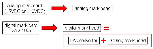
* All aboveanalogue marking heads can be converted into digital marking heads via a D/Aconvertor.